
4: Greenwich village Maisonette renovation: construction docs

Clipping of Early Construction Documents
Construction Documents – Blueprinting the Build
After completing Design Development, we had a well-defined plan for this Greenwich Village renovation. The next step was to translate every aspect of that plan into formal Construction Documents (CDs) – the detailed drawings and specifications that contractors will use to price, pull permits, and actually build the project. If earlier phases were about what we’re going to do, the Construction Documents phase is about how exactly we’re going to do it.
Think of Construction Documents as the instruction manual for the renovation. These documents cover everything from the big-picture layout down to the minute details of trim and fasteners. For a project like this, the CD set becomes quite extensive. It’s not just for the contractors; it’s also scrutinized by plan examiners at the Department of Buildings and, in our case, the Landmarks Preservation Commission. Accuracy and clarity are paramount – any ambiguity can lead to mistakes or delays on site.
Let’s break down what went into our Construction Documents and how we tailored them for this historic maisonette renovation:
What Goes Into a Construction Document Set?
A full construction document package is composed of multiple types of drawings and written documents. For this project, our CD set included:
Cover Sheet & General Notes: The first page provides an overview. It lists the project title, address, client, and the design professionals (architect, engineers). It includes a drawing index (so anyone can find their way around the set) and general notes/codes used. For example, we noted: “All work to comply with the 2025 NYC Building Code, NYC Energy Conservation Code, and LPC guidelines for historic properties.” We also made clear which sheets were prepared by us vs. by consultants (structural, etc.), and that our set was to be filed for a building permit.
Existing and Demolition Plans: We included plans that showed the existing layout (to document starting conditions) and separate demolition plans highlighting what would be removed. On the demo plan, we clearly marked walls to be demolished with bold hatch patterns and wrote notes like “Remove existing plaster ceiling – salvage decorative medallion for reinstallation” to ensure anything historically important that was coming out was carefully preserved. These drawings are crucial for the contractor to understand how to strip the space before building anew. For a historic project, we made sure to specify protection measures on the demo drawings, such as covering that staircase and those Tudor windows during construction to prevent damage.
Proposed Floor Plans: These are the central drawings that show the new layout in detail. For each floor of the duplex, we drew dimensioned plans showing walls, doors, cabinetry, plumbing fixtures, appliances, etc. Every wall had a thickness, every door had a swing, and each room was labeled (e.g., “Master Bedroom,” “Parlor/Living Room”). We added key annotations: for instance, a note on the plan in the kitchen, “Remove portion of wall to create opening, see structural drawing S-3 for beam detail,” or in a bathroom “New plumbing chase, see section A on A-6 for construction.” We also indicated built-ins, electrical outlets/switches (though detailed in electrical plans, major ones were shown for coordination), and finishes (e.g., we hatched tile areas on the plan).
Reflected Ceiling Plans (RCPs): These drawings show the ceiling design, essentially a view of the ceiling layout as if looking down from above. Our RCPs detailed any soffits or dropped areas for ductwork, the location of ceiling light fixtures, and the placement of smoke detectors and sprinkler heads. For example, in the living room RCP, we outlined the new coffer that hides the beam and placed the new recessed lights symmetrically within it, also marking the decorative chandelier in the center. We noted ceiling heights (like “Ceiling Height = 9’-6” AFF except where soffit at 8’-10” AFF**”). These plans ensure all overhead work is coordinated.
Elevations: Interior elevations are like looking at a vertical slice of the walls in each room – very useful for kitchens, bathrooms, and any area with complex wall treatments or built-ins. We drew interior elevations for the kitchen (showing each wall with cabinets – specifying heights, widths, and the design of cabinet doors, open shelves, etc.), bathrooms (laying out tile patterns, wainscot heights, medicine cabinet positions, lighting sconces on the wall, etc.), and custom millwork units (like the Murphy bed unit, showing the panel layout and how the doors conceal the bed). For instance, the elevation of the Murphy bed wall showed the Tudor-arched panel motifs and the integrated bookshelves and desk. We keyed these elevations to the floor plans with marks so that the contractor could easily cross-reference.
Building Sections and Details: We cut a couple of key sections through the building – essentially a slice from roof to foundation – to show how everything aligns vertically. One section cut through the staircase, which let us illustrate the headroom clearance, the relationship of the stair to the new office wall, and how the new skylight above the stair (yes, we ended up adding a small skylight after LPC gave a nod) would bring light in. We also produced numerous detail drawings at larger scales to show exactly how things get built. For example, a detail at 1.5”=1’-0” scale of the new window trim meeting the existing brick wall, with insulation and flashing details to ensure it wouldn’t leak. Another detail showed how the new beam in the living room ceiling would be boxed out with wood and crown molding to appear as a decorative coffer. We also detailed things like the connection of the new glass shower enclosure to the old masonry wall – specifying anchors and sealants that protect the old tile.
Schedules: We included several schedules (charts) to complement the drawings:
Door Schedule: Listing every door by number, with info on size, type, material, fire-rating (if any), hardware set, and notes (e.g., “Door D-3: Existing 1840s wood door to be restored and reused at Bedroom. Provide new hinges and lockset.”).
Window Schedule: Since we were restoring some and replacing others, this schedule specified which windows get what treatment. For each window we noted dimensions, type (double-hung, casement, fixed), material (existing wood/new wood), glass type, and any LPC stipulations (like “Replace in kind per LPC approval”).
Finish Schedule: A room-by-room listing of floor, wall, and ceiling finishes. For example, Entry Foyer: Floor – Refinished original pine with stain #X, Walls – Paint (Benjamin Moore HC-… color), Ceiling – Paint (white), Trim – New wood to match existing, paint semigloss white. This gave the contractor a clear guide for each space.
Lighting Schedule & Fixture Cuts: We enumerated all light fixtures (by a tag corresponding to the electrical plan) with description and manufacturer info. For decorative fixtures like the salvaged chandelier, we included a note: “Owner-supplied antique chandelier, contractor to rewire to code and install.” We attached spec sheets (cut sheets) for all new fixtures so the electricians know what they’re installing.
Plumbing Fixture Schedule: Similar to lighting, we listed each plumbing fixture (sinks, toilets, tub, shower system) with model numbers, finishes, and any special notes (e.g., “Tub filler to have floor-mounted supply lines, include in pricing”).
Mechanical, Electrical, Plumbing (MEP) Plans: While our MEP engineers produced their own detailed drawings (which became part of the overall set), we coordinated closely with them. These plans showed the ductwork layout, HVAC unit placement, pipe routing, electrical circuiting, panel schedule, sprinkler head layout, etc. For instance, The HVAC plan indicated the run of ducts between floors, the fan-coil unit's location in a closet's ceiling, and the outdoor condenser on the roof (with the path of refrigerant lines). We added a note that the condenser placement was subject to condo and LPC approval (though not visible, we always cover our bases).
The electrical plan mapped out every outlet, switch, fixture, and the path to the breaker panel, with loads balanced and circuits labelled. We included a panel schedule listing each circuit’s breakers and what they serve (useful for DOB filing and the electrician’s work).
The plumbing plan showed new water lines (hot/cold) running from the risers to each fixture, waste lines to the building stack, and vents. We detailed how the new upstairs kitchen waste ties into the downstairs line that connects to the building's main. We also showed where access panels needed to be placed to reach valves or clean-outs (particularly important in concealed locations).
Specifications (Project Manual): Alongside the drawings, we compiled a specifications document – essentially written instructions covering materials and workmanship not easily conveyed on drawings. This includes general requirements (quality standards, insurance requirements, etc.), and technical specs for each trade. For example, for plaster repair, we specified the method and materials (we wanted a lime-based plaster mix for patching original walls to match them, rather than standard modern gypsum in certain areas). We specified that all woodwork should be primed on all sides before installation (to reduce moisture movement). We also outlined procedures: e.g., if asbestos was found during construction (we’d already tested, but just in case), work must stop and a certified abatement contractor must be engaged. The spec is the place for such protocols and references to regulatory compliance (like referring to the LPC permit requirements, or condo rules for construction hours).
With all these pieces, the CD set for this project ended up being on the order of 40+ sheets of drawings plus a thick specification booklet. It might seem excessive to some, but this level of detail is what ensures that the contractor’s only questions during construction are minor – because we’ve already answered the big ones on paper.
“In a landmarked building, these documents must reflect any requirements set by the Landmarks Preservation Commission (LPC)—especially for exterior changes or modifications to protected interior features.”

An extremely pared back version of what construction documents start to look like. The actual complete set, after coordination with the various design professionals contains more than forty 24” × 36” sheets.
Highlighting Historic Elements in the Drawings
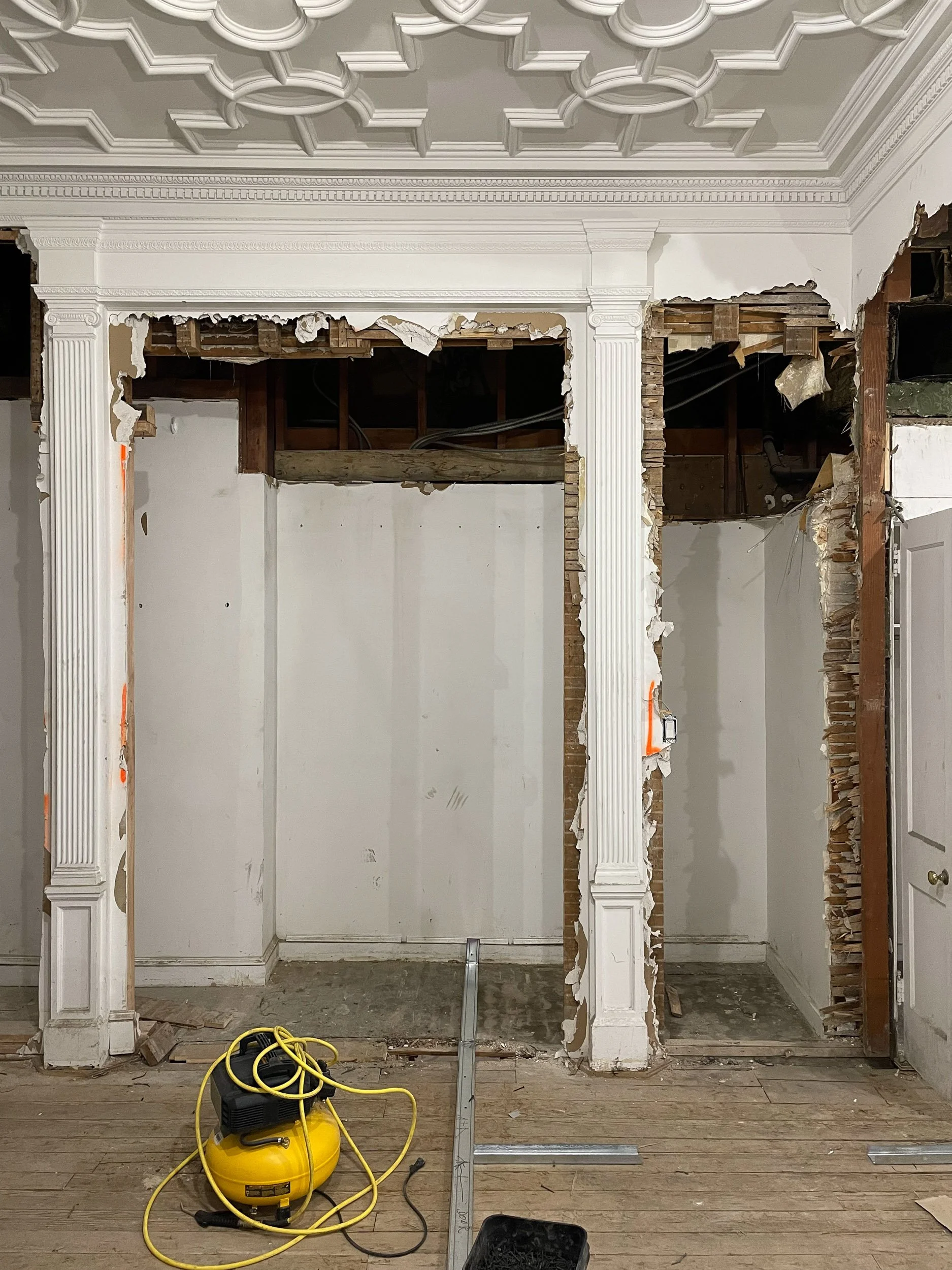
Preserving these details the above image is noted in at least 5 different places, the bid letter, the demolition plans, the demolition elevations, the construction documents and the interior construction elevations—this way if a subcontractor is doing the work and only looking at (1) sheet in particular there’s no way there’s a misunderstanding. To reinforce these efforts, after the General Contractor, was brought on board, they marked out the walls to be removed and the parts to be left, you can see the orange marks on what remains.
Given the historic nature of the building, we put special effort into making sure the Construction Documents explicitly called out all the historic elements to be preserved or restored. This serves two purposes: it guides the contractor, and it demonstrates to Landmarks (and the condo board) that we are being diligent custodians of the property’s character.
Some ways we did this:
On our plans and elevations, any item that was original and to remain was tagged with a note like “Existing decorative plaster crown moulding to remain; protect during construction, patch and repair as needed” or “Original fireplace mantle (circa 1840s) – do not disturb, refinish in place.” These notes were repeated in multiple relevant drawings so they wouldn’t be missed. For example, the same note about the fireplace mantle would appear on the demo plan (to say “do not demo”), on the construction plan (to say “protect and refinish”), and on the interior elevation of that wall (to illustrate what final outcome we expect). Repetition is intentional – on a large set, a subcontractor might only look at one sheet, so we make sure critical instructions are hard to miss.
We included a dedicated sheet of restoration details. We had blown-up drawings of some of the historic components on this sheet. One drawing showed the profile of the existing baseboard vs. the new matching baseboard (with dimensions), and one showed how to patch the parquet flooring in an old parlour with salvaged wood from elsewhere (complete with a recommended pattern for weaving new boards into old). Another depicted the window restoration methodology: labelling parts like sashes, casing, weights, and providing a general note that windows numbered W1-W5 were to be carefully removed, stripped of paint, repaired (with any rotten wood replaced in kind), weatherstripped and reinstalled with new insulated glazing if approved by LPC. This sheet served as the “historic preservation scope” at a glance. It’s not typical for every project, but on this one it was worthwhile.
Where we introduced new elements that mimicked old ones, we cross-referenced. For instance, on the detail of the new crown moulding, we added a note “Profile to match existing crown in Living Room (see Detail 5/A-15).” The contractor then knows to literally take a piece of existing crown or the dimensioned detail we provided and replicate it for the new runs. We also specified if they needed to custom-mill something or if they could use a catalogue profile – in one case, the existing door casings were very simple, so we noted a stock profile from a manufacturer that was 95% similar to save cost, figuring that a minor difference is imperceptible.
Importantly, we emphasised LPC requirements wherever applicable on the drawings. For example, on the exterior elevation, we wrote: “All work at exterior (new window installation, rooftop equipment, etc.) is subject to LPC review and approval. The contractor will comply with LPC permit stipulations and use approved materials/finishes.” This ensures that when the contractor goes to do that work, they remember there’s another authority involved. We also indicated that any substitutions on those elements would have to be re-reviewed – e.g., “No substitution on landmark-approved windows; use manufacturer and model as specified or equal approved by architect/LPC.”
Documenting historic considerations in this way paid off. When we sent the set to the LPC staff as part of our Certificate of No Effect application, they commented that the drawings were very clear about what was happening to historic fabric (which likely helped our application move faster, since it gave them confidence that nothing nefarious was slipping in).
1. Preserving Historic Elements in the Drawings
Window Details: Each of the Tudor windows was called out in a window schedule with notes on restoration vs. replacement (if allowed).
Moldings & Trim: We included section details for existing Greek Revival moldings so contractors would replicate them if any had to be replaced.
Door & Hardware: Original 19th-century doors required special hardware references—some found through salvage resources or custom fabrication.

Co-op boards are often times the most challenging internal bureaucratic systems to work around. To put the board at ease, we did another 3D Matterport Scan of the entire basement, then modelled it to show our proposal. Its piping, electrical systems, gas lines, plumbing lines, and structures in the basement were all measured automatically then built upon so there would be fewer surprises. This also made coordinating the efforts of the Mechanical, Electrical & Plumbing much easier and more palatable for the board members to understand, as opposed to just line drawings.
2. Coordinating Mechanical, Electrical, and Plumbing (MEP)
Coordinating the MEP systems in a historic building renovation is like conducting an orchestra – many instruments (systems) playing in harmony without overpowering the melody (the architecture). Our construction documents needed to clearly convey how these new systems would be woven into the old structure.
We worked closely with the MEP engineers to ensure their drawings reflected the plan we all agreed on, and then we integrated key information from those drawings back into our architectural set where needed:
HVAC (Heating, Ventilation, Air Conditioning): On the mechanical plans, every duct run, return grille, and equipment piece was shown. We specified the type of grilles/registers to use in finished spaces (opting for low-profile, paintable ones that could blend into ceilings or walls). We coordinated the placement of thermostats on our plans (making sure, for instance, not to put a thermostat on a plaster feature wall or where it would look odd – instead, we chose side walls out of main sight lines). We also ensured the access panels for the fan-coil unit and dampers were indicated – no one wants a random panel cut into a beautiful ceiling without planning. We had a detail for how to integrate an access panel into the coffer so it was flush and hidden in a decorative pattern.
Electrical: We cross-referenced the electrical layout with our interior design plans. For instance, we made sure there was an outlet planned in the floor of the living room for a lamp by the sofa (we knew from furniture layouts that no wall was nearby for a plug). We indicated the exact height of outlets in areas with wainscoting or panelling, so the electrician would install them aligned neatly (or horizontally in baseboards where we wanted to hide them). On the lighting side, we included the switching plan, which switches control of which lights, so that the electrician wires it logically (and the end-users don’t end up with a confusing set of switches). For example, one 3-way switch at the bottom and top of the stairs controls the chandelier in the stairwell, etc. All of these were labelled on the plans and schedules.
Plumbing: The drawings specified pipe sizes, slopes, vent, and fixture connections. In our drawings, we flagged any areas where plumbing work might affect historic finishes, like chasing a new pipe through a plaster cornice area. For those, we coordinated a slight reroute to avoid cutting through decorative plaster, even if it meant a bit more pipe or elbow. Also, since noise can be a concern, we specified using cast iron for certain new drain lines (cast iron pipes dampen sound better than PVC – important when running through living spaces). We noted where to insulate pipes for condensation or sound. The mechanical plan also included a small sprinkler layout for the few heads we were adding – we coordinated those locations with our reflected ceiling plan to ensure they weren’t smack in the middle of an ornate ceiling detail.
Special Systems: The clients also requested modern features like a security system and smart home controls. These don’t always appear explicitly in architectural drawings, but we accommodated them. We had the electrician run empty conduits in walls to locations for future security cameras and alarm keypads (noted on plans as “Provision for security by others”). We showed where to put a central AV rack (in a closet) and coordinated outlets and cooling for that equipment. These are the kinds of things that if not planned, the contractor might start cutting unexpected holes late in the project to add them – so we try to foresee and document as much as possible.
One thing we did, that might interest condo owners, was to coordinate a lot with the building’s existing systems. The building had an antiquated intercom, and we wanted to integrate the apartment’s front door release into the new smart system – we created a diagram for the electrician to interface the new with the old, which saved a headache for them trying to figure it out on site. We also had to coordinate with the building’s main sprinkler supply for our new branch – that meant carefully detailing a connection in the basement plan (which ironically meant including one sheet that showed a portion of the building basement where our new valve would tie in – unusual for an apartment renovation, but needed because that work extends beyond our unit).
By coordinating all these and documenting them clearly, we aimed to avoid the common pitfall of old-building renos, where mechanical or electrical work compromises the design because it wasn’t fully thought out. Our CDs essentially left breadcrumbs for the contractor to achieve the technical requirements without undue damage or rework.

The above is one of many examples of bathroom layouts approved by the Department of Buildings. New York City takes Accessibility very seriously, and a number of homeowners are surprised to discover that these codes apply, if you’re renovating any sort of multi-family building over 4 stories, confirm which rules apply when as these are non-negotiable.
Ensuring Accessibility & Code Compliance
In the final construction documents, we made sure to incorporate all the code-compliance measures and future-proofing features we had planned during design:
Clearances & Dimensions: Every critical dimension that relates to code (and accessibility where applicable) was clearly dimensioned on the plans or elevations. Door clear width was noted (particularly for that powder room which we made as big as possible – we got a 32” clear door there, which is the ADA minimum for a door, even though it’s not a fully ADA unit, it’s a good practice). We drew the required grab bar reinforcement locations on the bathroom elevations (dashed lines showing where blocking exists behind the tile at 33-36” AFF around toilets and in showers). This is not a code requirement for a private residence, but we included it as a feature – and documenting it ensures the contractor actually puts the backing in during framing.
Stair Details: The staircase was a focal point, but also a code focus. We included a fully dimensioned drawing of the stair, showing tread runs and riser heights, the handrail profiles, mounting heights (we had to modify the original handrail to meet the 34–38” height requirement – it was at 32” originally – so we detailed a plinth to raise it slightly in a historically sensitive way). We also detailed the guardrail at the top (the railing around the stair opening on the upper floor), ensuring the spacing between balusters met the 4” sphere rule (we had to add a subtle acrylic panel on the inside of the existing historic balusters because they were wider spaced – LPC approved it since it was nearly invisible, and it made it safe). Those nuances all went into the drawings.
Fire Safety Details: We indicated where smoke/CO detectors go – outside bedrooms, inside bedrooms (required for hardwired systems in renovations), and one on each floor. We included an egress plan diagram that, while not required, illustrated the exit paths and that we satisfy the requirement of two means of egress from the duplex (in our case, one was the main apartment entry to the street, and a second was technically through the basement level directly outside – a bit unorthodox but permissible since the lower level had a door to the outside courtyard leading to a street). We also specified fire-rating assemblies where needed: e.g., the new wall we built between the mechanical closet (housing that HVAC unit) and the neighbor’s unit we made a 1-hour fire separation with fire-rated gypsum board, just as a precaution exceeding code (multi-family code often requires some separation between units anyway). We showed details for any penetrations through rated assemblies (like how to fire-caulk around a pipe).
Energy Code Compliance: We prepared the required energy analysis (Manual J for HVAC sizing, and lighting power calculations, etc.) in the background and made sure all those measures were reflected. For instance, to comply with the energy code on lighting, a certain percentage of permanent fixtures must be high-efficacy (LED/fluorescent) – since we were all LED, we were fine, but we noted it on the drawings: “All lighting to be LED or equivalent high-efficacy.” The insulation we added was noted with R-values on the sections (e.g., “R-15 spray foam between joists at roof”). We also had to incorporate a smart thermostat and some form of ventilation for good air quality – we actually added a continuous exhaust fan in the bathroom that operates very quietly to draw in fresh air under the front door (this strategy meets code for ventilation in some situations). The electrical drawings showed the energy code-required wiring for a future thermostat and shutoff for AC, etc.
By covering these in CDs, we were ready for the DOB plan examiner. In fact, when we submitted, we got minimal objections – mostly just typical paperwork clarifications – because our drawings already answered the life safety and code questions clearly.
Construction Documents Mini-Checklist
-
Assemble a full set of architectural drawings (plans, sections, elevations, details) and integrate consultant drawings (structural, MEP). Ensure all are coordinated – no inconsistencies in dimensions or scope between plans. For instance, if the structural engineer added a column, make sure it appears in the architectural plan and is accounted for in cabinetry, etc. Conduct an internal “sheet check” to verify everything aligns.
-
Provide schedules for doors, windows, finishes, fixtures, and equipment. These act as a master checklist for the contractor. It should be crystal clear how many of each item, what type, and where they go. If a door is re-used, label it existing; if new, specify material and fire rating if needed. Finish schedules should specify product or at least standards (e.g., “bath floor tile – 1” hex mosaic, DalTile Keystones or equal, color: Arctic White”).
-
Include or attach a project manual with specifications. This covers general conditions, quality standards (e.g., wood floor install per NWFA guidelines, tile per TCNA methods), and product specs that aren’t in the drawings. If you expect the contractor to follow a certain sequence or method (like a required chemical paint stripping process on wood trim to avoid damage), put it in the specs. Also list acceptable manufacturers for major items (especially things like windows, HVAC units, etc. that might get substituted).
-
Explicitly call out all items to remain and how to handle them. Use bold or unique symbols to denote “protect in place” items. If any restoration work is included (like “restore plaster medallion”), describe the expected method or outcome. This helps when obtaining Landmarks approval too, as they’ll see you have a plan to care for the historic elements.
-
Prepare any additional diagrams or forms needed for code compliance. In NYC, this means filling out forms like the TM (technical report forms for sprinklers, energy, etc.), and creating a DOB energy analysis worksheet if not using an energy model. Sometimes we include a life safety plan highlighting exits, extinguisher locations (if needed), etc., even if the job is small. If a licensed special inspector is required for certain tasks (concrete, steel, asbestos, energy compliance), note on drawings or specs that those will be engaged – often a DOB requirement.
-
Cross-check the CD set against the condo’s alteration agreement one more time. Make sure any notes they require (like sound underlayment, hours of work note) are clearly on the drawings so the contractor can’t claim ignorance. Before finalizing, we actually sent a courtesy PDF of the near-final CD set to the board’s architect for a last look – and incorporated one or two of his minor suggestions (he wanted a note about using only padded carts in the elevator, so we popped that into our logistics section)
-
It’s a lot of information, but walk the client through the highlights of the Construction Documents to get their sign-off. Confirm that all materials and layouts are exactly as expected. This is their last chance to tweak before it goes to bid and permit. In our case, we walked them through and the client was thrilled, making only one small request: to change the swing of a closet door – which we did.
-
With CDs done and signed off, submit the package to the DOB for permit (and to LPC for their final certificate, if you haven’t already during CDs). Respond to any plan examiner comments – our thoroughness paid off with minimal comments, which we addressed promptly. Obtain the permit. Also, submit the set to the condo board formally for their records and final approval sign-offs (they usually have a form to sign acknowledging they reviewed the final plans).
-
While waiting for permit approval, you can already start preparing the bid package for contractors using the CD set. We compiled a list of qualified contractors and prepared an invitation to bid, including our drawings and specs. Essentially, by the time our permit was ready, we were also ready to break ground with a contractor selected – but that’s getting into the next phase…
Next Step: Bidding, Negotiation & Permitting
Once the Construction Documents are locked in, it’s time to put the project out to bid. We’ll simultaneously juggle permits from the DOB, landmark approvals, and the condo board’s final sign-off. This phase can feel like a three-ring circus—but with a thorough set of CDs, at least we know exactly what we’re asking contractors to price.